UEFI is the new BIOS
UEFI Reverse Engineering, Vulnerability Discovery, and Exploit Development: Part 0
By Nika Wakulich
This blog post is the first in a series on UEFI reverse engineering, vulnerability discovery, and exploit development.
The full list of all parts of this blog series is provided below. New blog posts will be added in the coming weeks and the associated links will be added to this list when posts are added:
Part 0: Introduction
Part 1: UEFI Entomology 101 – UEFI Bugs
Part 2: UEFI Lab setup
Part 3: Static analysis of UEFI firmware
Part 4: Dynamic analysis of UEFI firmware
Part 5: Fuzzing UEFI firmware
Part 6: UEFI Exploit development Overview – Introduction to methodology and initial development of PoCs
Part 7: UEFI Exploit development testing and debugging – software and emulation
Part 8: UEFI Exploit development testing and debugging – hardware testing and debugging techniques
Introduction
Once upon a time, in the golden age of rootkits and the dawn of the mainstream adoption of the internet, the wild malware threat landscape was overrun by MBR bootkits and exploits targeting the famously insecure pre-OS boot environment of legacy BIOS (Basic Input-Output System) machines. But after the mainstream adoption of UEFI (Universal Extensible Firmware Interface) changed the malware threat landscape forever, a natural question arose: with the new advancements in platform firmware design and implementation, what was a bootkit developer to do? Surely, with this new shift in the paradigm, boot process security was a thing of the past… right?
I’ll let you in on a secret though: BIOS hacking is back, and it’s badder (and better) than ever. Although UEFI introduced novel innovations and hitherto unforeseen developments in the boot process, and thus mitigations for classic MBR bootkits, a new era was about to begin – the era of UEFI exploits, UEFI-based bootkits, and UEFI firmware implants.
If a bootkit developer wants to move forward into this new era, however, they’ll need a new skillset. While an understanding of legacy BIOS, MBR, and the boot process of days past provides a significant leg up on the competition, and lays a solid foundation for identifying vulnerabilities in the boot process and pre-OS environment, an understanding of UEFI is critical.
Here at Leviathan, we’ve been hard at work building up our knowledge and skillsets in UEFI reverse engineering and exploit development and implementing new processes to find and exploit UEFI vulnerabilities on our engagements with clients. And I’m here to teach you about UEFI reverse engineering and exploit development so that you too can build the skills necessary to find and exploit UEFI bugs, understand common UEFI vulnerabilities, and better secure the firmware security supply chain.
Even for seasoned exploit developers, UEFI exploit development often has an air of both intrigue and impenetrability. UEFI not only defines an interface specification for the platform firmware responsible for the boot process of modern devices, but also encompasses a vast and complex landscape of the platform initialization components. The discrete platform components of a legacy BIOS machine now all fall under the singular umbrella of UEFI. This is a double-edged sword for a reverse engineer or exploit developer: Although the expansive attack surface of UEFI provides ample opportunities for finding vulnerabilities, its complexity necessitates a roadmap to effectively navigate that landscape.
This blog post series is intended to provide one such roadmap. By the end of this series, you will be better equipped with the foundational knowledge of UEFI and UEFI vulnerabilities necessary for successful UEFI reverse engineering, vulnerability discovery, and exploit development.
The term “UEFI vulnerabilities” encompasses bug classes that can originate in either firmware or hardware.[1] Regardless of a UEFI vulnerability’s origin, it is important to understand that a successful UEFI exploit can have far-reaching effects beyond the boot process. Attackers can leverage these vulnerabilities to perform exploits with devastating impact, including but not limited to installing persistent firmware implants or bootkits, bypassing OS-level security mitigations and access controls, and remaining undetected to all but seasoned firmware forensics experts.
This series introduces the various components of UEFI relevant to our purposes: successful reverse engineering, vulnerability finding, and exploit development targeting UEFI firmware. While I will cover many different aspects of UEFI, it’s important to note that this overview of UEFI/PI is not comprehensive, since covering every detail could fill volumes. I encourage readers to check out the additional references listed in the References section at the end of this article.
From Legacy BIOS to UEFI
The UEFI specification defines a platform-agnostic implementation for an interface between platform firmware and an operating system (OS). Although UEFI encapsulates functionality that extends beyond platform initialization and OS bring-up, to quote the great Vincent Zimmer[2] , “In general … UEFI is about booting or passing control to a successive layer of control, namely an operating system loader” (Zimmer, “Beyond BIOS,” page 1) [1].
The UEFI specification only defines an implementation for the platform-agnostic firmware and OS interface beginning at the DXE phase. What is commonly referred to as the “UEFI boot process” really means the UEFI/PI boot flow. PI stands for Platform Initialization, and it has its own separate specification under the UEFI Forum umbrella. We can see in Figure 1a that PI encapsulates the SEC and PEI phases of the boot flow. In this section, we’ll cover all the phases of the UEFI/PI boot flow.
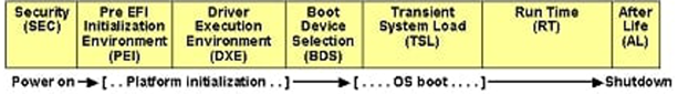
Figure 1a. UEFI/PI Boot Process phases (Image source: (https://uefi.org/specs/PI/1.8/V2_Overview.html)
Before we begin digging into UEFI, let’s take a quick detour to brush up on the history of BIOS implementations.
It’s all well and good to say that UEFI is a replacement for “legacy BIOS,” but understanding what legacy BIOS is, and how it differs from UEFI, is important for contextualizing the modern UEFI threat landscape. Furthermore, understanding the differences between legacy BIOS and UEFI will help you in your role as a reverse engineer, exploit developer, or researcher. To provide some important context and clear up some confusion on terminology, let’s start by expanding on what we mean when we say “legacy BIOS.”
Up until the initial adoption of EFI/UEFI (circa the late 1990s-2000s), legacy BIOS defined the non-standardized standard for BIOS implementations. BIOS is platform firmware responsible for configuring hardware and performing all necessary preparations to ensure that the system’s state is ready before loading an operating system.
Here, we will more appropriately define “legacy BIOS” to mean the specific Independent BIOS Vendor (IBV) proprietary implementations of BIOS code.
BIOS code was also referred to as the boot-block-code, and it is notably different from what we see today in UEFI in multiple ways, several of which are highlighted here:
Legacy BIOS code was written in 16-bit assembly and run in real mode.
Each legacy BIOS implementation was IBV-specific; each major IBV (e.g., AMI, Phoenix) had a proprietary BIOS implementation. Since there was no standard BIOS spec, each IBV’s proprietary BIOS was notoriously tricky—though not impossible—to reverse engineer.
Finally, although legacy BIOS was responsible for performing system-critical functionality, including initialization of platform hardware and firmware in preparation for loading an OS, it was limited in scope and size due to the restrictions of the pre-OS environment in a legacy BIOS system as well as the hardware constraints of older machines.
Refer to “Rootkits and Bootkits”[2] and “Beyond BIOS”[1] for more details.
It is important to note that legacy BIOS is not an extinct technology. Though increasingly uncommon, legacy BIOS is still used on systems today. Due to the proprietary nature of legacy BIOS implementations, there are few resources available to aid the avid reverse engineer or exploit developer as they parse all the 16-bit real-mode code of the BIOS and slowly start to fit the pieces together to craft an exploit.
One outstanding resource on this front is “BIOS Disassembly Ninjutsu Uncovered,” by Darmawan Salihun (pinczakko) [3]. The first edition of this book is freely available on pinczakko’s GitHub: https://github.com/pinczakko/BIOS-Disassembly-Ninjutsu-Uncovered. This book has been an invaluable resource to us on the rare occasions that we come across a legacy BIOS on an engagement and want to develop a BIOS-specific exploit written in 16-bit assembly.
In contrast to legacy BIOS, which was implemented per IBV, UEFI offers a platform-agnostic interface specification for the boot process and platform initialization. It defines a core set of components and features that are common across all UEFI implementations while also offering the extensibility of a platform firmware build customization. Thus, IBVs, OEMs, and other entities can implement custom UEFI firmware that conforms to the UEFI spec. This is an important shift from legacy BIOS, which (as noted above) is more difficult to reverse engineer due to factors such as its often hyper-specific implementation, lack of documentation of vendor-specific BIOS code and features, and non-uniform binary formats.
Finally, while the mainstream adoption of UEFI across the industry continues to push legacy BIOS ever closer toward obsolescence, it is important for researchers to have a strong grasp on the legacy BIOS boot process for several reasons:
Features of the legacy BIOS boot process remain part of UEFI (e.g., the legacy MBR still remains at Cylinder 0, Head 0 Sector 1 on disk), and the legacy MBR is integrated into the GUID Partition Table (GPT). Understanding the components or processes of legacy BIOS that remain a part of the UEFI boot process is essential to having a solid grasp on the myriad components of the UEFI boot process and UEFI BIOS implementations overall.
Malware continues to target legacy BIOS systems in conjunction with systems using a UEFI BIOS due to the ghostly apparition known as tech debt that haunts us all.
The UEFI/PI Boot Process: Phases of UEFI/PI Boot
Fast forward to today, UEFI is the industry standard, and these PoCs aren’t going to write themselves, so let’s dive in.
UEFI is a rich ecosystem that encapsulates a staggering depth and breadth of functionality in comparison to its predecessor. Along with that depth and breadth comes a larger attack surface. For us firmware and hardware reverse engineers, this is like being a kid an entire candy factory!
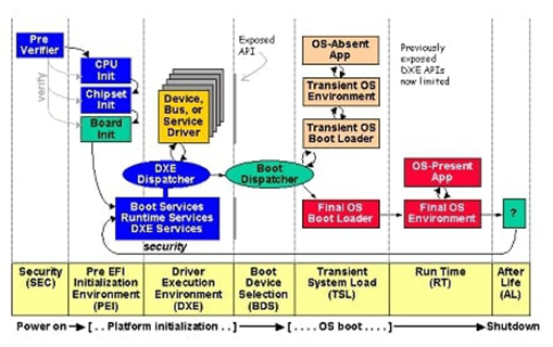
Figure 1b. UEFI/PI Boot Process phases and environment (Image source: https://uefi.org/specs/PI/1.8/V2_Overview.html)
Let’s cover some basics relevant to our understanding of the UEFI ecosystem. We’ll start at the beginning – the reset vector.
The UEFI PI boot process is comprised of multiple phases (see Figure 1b). We’re going to dig into the first four phases (SEC, PEI, DXE and BDS) now because they define the platform firmware initialization environment. This finer-grained knowledge of the UEFI PI boot process will be essential to understanding how unique attack surfaces manifest in these early platform firmware initialization phases. For additional information on the UEFI PI boot process, refer to [12] and [13] in the References section.
To provide context for how the code of each of these phases is divided in the BIOS region of an SPI flash chip, I’ve also included screenshots of a UEFI BIOS firmware image (UEFI BIOS for the X58I reference platform from the edk2-platforms repository) loaded into UEFITool (see figures 2, 3, and 4 below). We’ll cover UEFITool and its useful features in a later post in this series when we cover UEFI lab setup. For now, it’s sufficient to know that UEFITool is an open-source UEFI firmware image viewer and editor that we can use to open a desired BIOS image and parse its various components.
Security (SEC): This first phase of PI handles all system restart events, initializes temporary RAM for the PEI phase, and passes important data to the PEI Foundation.
SEC phase code resides in its own dedicated firmware volume on the SPI flash. We can see in Figure 2 below that the SEC phase code is comprised of only the SEC core. This small code size makes sense given the limited environment available during the SEC phase as well as the role of SEC phase code in preparing a minimal working environment for the PEI phase code.
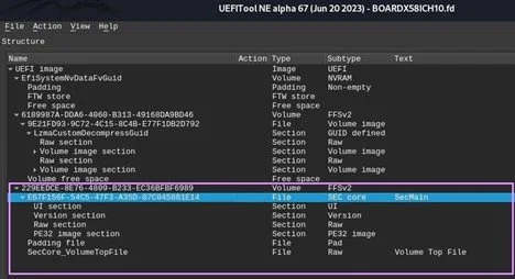
Figure 2. UEFITool view of Board X58ICH10 UEFI BIOS - SEC phase code
SEC is also responsible for “serving as the root of trust in the system” [4]. This is a loaded statement on its own, even without it being in reference to a phase called “Security.” To understand the complexity of this, we need context: The viability of SEC as a root of trust for the system fluctuates depending on which, if any, platform firmware security mechanisms have been enabled (e.g., Intel Boot Guard, Intel BIOS Guard.)
I’ll cover the variations in Secure Boot implementations (i.e., UEFI Secure Boot, Intel Boot Guard, and Intel BIOS Guard) shortly, but for now, suffice it to say that SEC in some way serves as the root of trust in a chain of trust for platform firmware integrity verification. However, the robustness of this chain of trust is dependent not on SEC itself, but on the prior application of platform firmware security technologies.
In summary, the SEC phase is primarily responsible for preparing the minimal environment needed by the PEI phase, rather than being a robust initial phase for locking down system security. SEC phase code mainly handles platform restarts and prepares the temporary RAM used for PEI.
With the necessary conditions for PEI in place, let’s continue to that phase.
Pre-EFI Initialization (PEI): This is where things start to get interesting. PEI is an underappreciated and oft-neglected phase of the UEFI/PI boot process, but it provides a unique and rich attack surface all on its own.
PEI is primarily responsible for preparing the system such that control can be passed to the DXE phase. Are you sensing a theme here? Yes, each phase’s job is typically to prepare and configure the system for the subsequent phase, building upon the prior configuration. Let’s explore further what this means for the PEI phase a bit more.
PEI tasks:
Initialize permanent system memory for the DXE phase: The PEI phase code uses the temporary RAM that was initialized in the SEC phase until it has fully initialized permanent system memory
Initialize platform components: Modules in PEI are responsible for initializing discrete chipset components, ensuring that each hardware component has a minimal working environment with all its required dependencies met before control is transferred to the next phase of the boot process
Describe the architecture state using Hand-Off Blocks (HOBs): The PEI phase populates a list of HOBs during the PEI phase, and this HOB list is then passed to the DXE phase at the end of PEI. The HOB list provides the DXE phase with information about the state of the system and its various components prior to the beginning of DXE
Handling of recovery modes and handling of the S3 resume stat [13]
PEI phase code can be divided into two main groups: The PEI Foundation and PEIMs (see Figure 3).
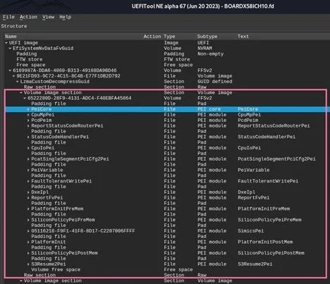
Figure 3. UEFITool view of Board X58ICH10 UEFI BIOS - PEI phase code
The PEI code, like the SEC phase code, also resides in a dedicated firmware volume within the SPI flash. However, as the system progresses in the boot process, moving from SEC to PEI to DXE and beyond, the size of the code for each phase increases. The increase in code size makes sense, as it parallels the increasing scope and functionality of each phase, as well as the increasing access to system resources and configured interfaces and data structures used by the code in each phase of the UEFI/PI boot process. As we can see in Figure 3, although the SEC phase code was only comprised of SEC core, the PEI phase code of the X58ICH10 UEFI BIOS contains the PEI core (also known as the PEI Foundation) and various PEI modules (PEIMs). As previously noted, one responsibility of the PEI phase code is to handle the S3 resume state. The last PEIM in the PEI firmware volume is “S3Resume2Pei,” which is the PEIM responsible for this very task (see Figure 3).
Let’s break down each of the components of the PEI phase code.
The PEI Foundation: This binary executable is responsible for managing all other PEI components and PEIMs and for setting up the necessary environment for communication between those components.
The PEI Foundation also encapsulates the PEI dispatcher, which is a specific phase within PEI that evaluates the dependency expressions of PEIMs and determines which of the PEIMs have their required dependencies met and can be loaded/run.
Pre-EFI Initialization Modules (PEIMs): These binary executables are responsible for initializing the chipset components. Each PEIM is a driver and is typically associated with a specific hardware or platform component. As already noted, there is a PEIM for the S3 resume state (S3Resume2Pei; see Figure 3), but PEIMs are also responsible for initializing other platform components. For example, Figure 3 shows the inclusion of PEIMs, such as “CpuIoPei” and “PlatformInitPreMem”, which are responsible for tasks implied by their names: the initialization of CPU I/O[3] and platform initialization prior to memory controller initialization,[4] respectively.
PEIM-to-PEIM Interfaces (PPIs): These are interfaces provided by the PEI Foundation that allow for communication between PEIMs. The PEI Foundation maintains a database of the PPIs and the interfaces that can be used by PEIMs to register each PPI [1, p. 214].
Although PEI is distinct from DXE due to its restricted and minimal environment and the differences in responsibilities under PEI versus DXE, PEI functions analogously to DXE in many ways. One example of this is how PPIs are registered and maintained by the PEI Foundation. As stated in the PI Spec, Chapter 2.7, “A consumer of a PPI must use the PEI Service LocatePpi() to discover the PPI of interest. The producer of a PPI publishes the available PPIs in its PEIM using the PEI Services InstallPpi() or ReinstallPpi().” [5]
This can be viewed as analogous to the services provided in the DXE phase for interacting with protocols (e.g., registering, uninstalling, reinstalling, locating protocols). The following services provided in the EFI Boot Services Table correspond to each of the aforementioned protocol services respectively: EFI_BOOT_SERVICES.InstallProtocolInterface(), EFI_BOOT_SERVICES.UninstallProtocolInterface(), EFI_BOOT_SERVICES.ReinstallProtocolInterface(),
EFI_BOOT_SERVICES.LocateProtocol().
We’ll come back to PEI and related PEI vulnerabilities later in this series. For now, let’s move on to the DXE phase. I explained how PEI is analogous to DXE in many ways, but what is DXE?
Driver Execution Environment (DXE): The DXE phase is the first phase covered by UEFI, and we are now officially in UEFI land! DXE phase code gets everything in the UEFI environment up and running. DXE code sets up the EFI System Table, EFI Boot Services Table, and EFI Runtime Services Table, the three key data structures in UEFI that contain pointers to essential UEFI data structures and functions. These three data structures work together to initialize the UEFI environment.
As part of the DXE phase, all EFI Boot Services, EFI Runtime Services, and DXE Services are initialized, so all functionality present therein is made accessible to the UEFI environment (see Figure 4).
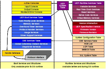
Figure 4. UEFI Data Structures initialized during DXE Phase
Image Source: UEFI PI Spec, Volume 2: DXE Foundation
(9.3. DXE Foundation Data Structures, Fig. 9.2 UEFI System Table and Related Components
https://uefi.org/specs/PI/1.8/V2_DXE_Foundation.html#uefi-system-table-and-related-components)
Later in this series, we’ll cover UEFI reverse engineering and exploit development in depth— we’ll really get to dig in to programming constructs, calling conventions and the nitty gritty of the UEFI API. However, as a primer, I have included the source code for a simple UEFI program below. The annotated source code provides additional context about what DXE phase code initializes, and the functionality provided by our power-player data structures: EFI System Table, EFI Boot Services Table, and EFI Runtime Services Table.
greetings.c is the C source code for a simple UEFI app that prints “Greetings from Leviathan” to the Console in the UEFI shell.
Example source code for greetings.c:
#include <Library/UefiLib.h>
#include <Library/UefiBootServicesTableLib.h>
#include <Library/UefiRuntimeServicesTableLib.h>

EFI_STATUS
EFIAPI
UefiMain (
     IN EFI_HANDLE          ImageHandle,
     IN EFI_SYSTEM_TABLE    *SystemTable //[1] Pointer to EFI_SYSTEM_TABLE passed in
     )

/*
* UefiMain does the following:
* [2] Calls SystemTable->ConOut->OutputString function to print “Greetings from Leviathan” to console
* [3] Retrieves pointer to EFI_BOOT_SERVICES table from EFI_SYSTEM_TABLE
* [4]Prints address of EFI_BOOT_SERVICES table to console – using the UEFI library function Print().
*/

{
     SystemTable->ConOut->OutputString(SystemTable->ConOut, L"Greetings from Leviathan\n"); // [2]
     EFI_BOOT_SERVICES *gBS=(SystemTable->BootServices); // [3]
     Print(L"Boot Services Table address is: %p \n\n", &gBS);  // [4]
     return EFI_SUCCESS;
}
Another important responsibility of the DXE phase code during system initialization is the initialization of the chipset and hardware. This might be confusing because PEI also covers initialization of platform components such as hardware, so let’s expand on what this means in the context of DXE. DXE phase code will either build upon the prior initialization of platform components performed during the PEI phase or perform initialization itself, or it will use some combination of the two.
However, DXE does not require the PEI phase to initialize hardware components, and DXE does not technically require the PEI phase at all. DXE phase code does require a HOB list, a data structure that can be created during the PEI phase. Again, quoth the PI Spec, “The DXE phase does not require a PEI phase to be executed. The only requirement for the DXE phase to execute is the presence of a valid HOB list. There are many different implementations that can produce a valid HOB list for the DXE phase to execute. The PEI phase in a PI Architecture firmware implementation is just one of many possible implementations.” [6]
DXE phase code isn’t a single standalone binary. Like the PEI phase, the DXE phase code can be divided into two groups: The DXE Foundation (which contains a component called the DXE Dispatcher) and DXE drivers (see Figure 5). The DXE Foundation and the DXE drivers are detailed next.
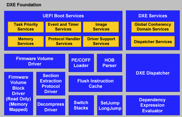
Figure 5. DXE Foundation Components
Image Source: UEFI PI Spec, Volume 2: DXE Foundation
(9.4. Required DXE Foundation Components
https://uefi.org/specs/PI/1.8/V2_DXE_Foundation.html#dxe-foundation-components)
DXE Foundation: The DXE Foundation (also referred to as the “DXE Core” in some literature [5]) is a boot service image responsible for setting up the aforementioned important tables (i.e., UEFI System Table, Boot Services Table, Runtime Services Table) and their corresponding DXE Services, Boot Services, and Runtime Services. The DXE Foundation encapsulates the DXE dispatcher that is responsible for discovering and executing DXE drivers and ensuring their dependencies are met.
DXE Drivers: These drivers initialize the platform, including the chipset and hardware, and setup of console I/O services. Since the DXE Foundation consumes the HOB list, DXE drivers can use that information to build upon prior initialization as well as initialize additional components. One notable example is that DXE drivers are typically responsible for setting up System Management Mode (SMM), which we will dive into later in this series.
Compared to earlier phases of the PI/UEFI boot process, DXE has an expansive environment, in large part made possible by its access to system resources, notably the newly initialized permanent memory that was set up in the PEI phase. We can applaud the DXE phase for ushering in such breadth and depth of functionality to our platform firmware interface. In the greetings.c sample UEFI app source code, we saw an example that scratched the surface of what’s possible for UEFI apps and drivers, but as we’ll see as we progress through the series, there’s much more complexity and flexibility offered to a programmer within the UEFI environment. As we leave the DXE phase, with the UEFI environment fully initialized, and move toward the OS runtime environment, it can be helpful to consider this new UEFI environment as a separate ecosystem (almost like an OS prior to the OS, a proto-OS, if you will).
Boot-Device Selection (BDS): The BDS phase can be thought of as the UEFI boot manager.
The BDS phase code performs important tasks such as enumerating possible boot devices, evaluating the boot order, and ultimately performing the final UEFI housekeeping before transferring control to the boot device – often the OS loader.
At the end of the BDS phase, a call is made to the function ExitBootServices(), which destroys the EFI_BOOT_SERVICES table. After this point, the EFI_BOOT_SERVICES functions can no longer be called. Notably, the EFI_RUNTIME_SERVICES table is preserved, and a user can access EFI_RUNTIME_SERVICES functions from the OS runtime environment. Thus, while the BDS is the “final” phase of UEFI, after which a significant portion of the UEFI API is no longer usable, the BDS phase does not destroy the UEFI environment completely. Because the EFI_RUNTIME_SERVICES table and its associated functionality is maintained through the next phase Transient-Stage Load (TSL) and ultimately through OS bring-up, a bridge for communication between platform firmware and the OS is preserved.
For a more formal list of BDS phase code responsibilities, refer to the UEFI Spec:
“The BDS phase is implemented as part of the BDS Architectural Protocol. The DXE Foundation will hand control to the BDS Architectural Protocol after all of the DXE drivers whose dependencies have been satisfied have been loaded and executed by the DXE Dispatcher. The BDS phase is responsible for the following:
Initializing console devices
Loading device drivers
Attempting to load and execute boot selections” [7]
Important note: The above overview of the phases of the UEFI/PI boot flow does not cover aspects of the boot process that occur prior to SEC, but a lot happens even before the first instruction of the SEC phase. This is particularly true when technologies such as Intel Boot Guard and Intel BIOS Guard are utilized (e.g., when Intel Boot Guard is enabled for a compatible system, then the Authenticated Code Module [ACM] will be loaded and executed prior to execution of the first instruction after the reset vector). Other platform components such as the Converged Security and Management Engine (CSME) play an important role in the Intel boot process but will not be covered in this blog post for brevity’s sake. Additional resources on CSME and prior CSME vulnerabilities and exploits is included in the References section.
Secure Boot and Platform Firmware Security Technologies
Now that we’ve discussed the main phases of the UEFI/PI boot flow, you may ask: How do we protect a UEFI BIOS from being modified, tampered with, or otherwise exploited by a threat actor? Enter Secure Boot technologies. “Secure Boot technologies” is an umbrella term that encompasses a variety of platform firmware security mechanisms designed to provide robust firmware integrity verification and lock down a UEFI BIOS as much as possible.
“Secure Boot comes in three forms, which depend on the level of the boot process hierarchy at which it’s enforced:
OS Secure Boot: Implemented at the level of the OS bootloader. This verifies components loaded by the OS bootloader, such as the OS kernel and boot-start drivers.
UEFI Secure Boot: Implemented in UEFI firmware. This verifies UEFI DXE drivers and applications, Option ROMs, and OS bootloaders.
Platform Secure Boot: Anchored in the hardware. This verifies platform initialization firmware.”
This helpful classification of the different varieties of platform secure boot technologies is from in “Rootkits and Bootkits,” in Chapter 17 “How UEFI Secure Boot Works” [8].
The following descriptions are a non-exhaustive explanation of some of the main the differences between the many Secure Boot and platform firmware security technologies. I will attempt to help you better understand how these technologies are implemented, what they protect, what they fail to protect, and how their use changes the platform firmware threat landscape.
Note: In this section, I will only focus on Secure Boot technologies for Intel processors. The three I’ll focus on are UEFI Secure Boot, Intel Boot Guard, and Intel BIOS Guard.
UEFI Secure Boot
UEFI Secure Boot is the most basic layer and protects the UEFI BIOS starting from the later stages of DXE onward. It provides protection and image verification at a point late in the process, beginning from SPI flash and continuing through to OS bring-up.
If UEFI Secure Boot is the only platform firmware security mechanism enabled, then SEC forms one part of the Initial Boot Block (IBB), which serves as the Core Root-of-Trust for Measurement (CRTM) [12]. UEFI Secure Boot relies on the integrity of two components as the root of trust: the IBB (SEC and PEI) and the Platform Key. The PI components (SEC and PEI) are stored in SPI flash and are implicitly trusted by UEFI Secure Boot. UEFI Secure Boot uses a Public key infrastructure (PKI) to verify the integrity of certain components of the UEFI BIOS firmware image. The main components of UEFI Secure Boot’s PKI include the db and dbx databases (used for storing known-good certificates/hashes of UEFI binaries and known-unsafe certificates/hashes of UEFI binaries, respectively) as well as the Key exchange key (KEK) and Platform Key (PK), both of which are used for verification of digital signatures [9].
A detailed breakdown of db database, dbx database, PK, and KEK, and their role in the UEFI Secure Boot process is beyond the scope of this article (for further information see Secure Boot and Platform Firmware Security Technologies Resources and References). For our purposes, it’s sufficient to understand that UEFI Secure Boot verifies only components of UEFI. Thus, it begins firmware integrity verification at the DXE phase. The IBB is implicitly trusted as secure because it forms the root of trust for UEFI Secure Boot. Therefore, although UEFI Secure Boot applies firmware security verification against any UEFI application or driver loaded in the DXE or BDS phases, it does not verify the integrity of SEC or PEI components.
Even from an initial design perspective, the design flaws in UEFI Secure Boot—and consequently, the avenues for bypass—are numerous. As an example, I have highlighted two main design features of UEFI Secure Boot that open the door for potential bypass of UEFI Secure Boot’s firmware image integrity verification mechanisms. These two examples are noncomprehensive, and there has been significant, excellent research done on this topic since Secure Boot’s introduction. Refer to the [Secure Boot and Platform Firmware Security Technologies Resources and References] section for further reading on Secure Boot bypass techniques.
The root of trust for UEFI Secure Boot is the PI firmware, which is loaded from SPI flash; if an attacker can gain SPI write access and modify the PI firmware on the flash, they effectively compromise the entire UEFI Secure Boot chain by owning the UEFI Secure Boot root of trust.
UEFI Secure Boot begins firmware security verification at the DXE phase. This makes sense because UEFI begins in the DXE phase, so UEFI Secure Boot should only be responsible for verification of its own components. Vulnerabilities in the PI firmware (i.e., PEI), however, could be exploited and leveraged to target either SMM (to write to SPI flash) or other components of platform firmware that are loaded prior to DXE.
In order to ensure UEFI firmware image integrity verification and measurement of all phases of the UEFI/PI code, we can turn to another more robust technology – Intel Boot Guard.
Intel Boot Guard
Intel Boot Guard surrounds UEFI Secure Boot, forming an encapsulating layer of firmware integrity protection and verification that extends the root of trust to cover all stages of the UEFI/PI boot flow. With Intel Boot Guard, platform firmware integrity verification now covers SEC and PEI phase code, as well as the DXE phase code covered by UEFI Secure Boot. In other words, Intel Boot protects the UEFI BIOS from the earliest point in the process as it moves from SPI flash and then progressively through the earlier phases of the UEFI/PI boot process, finally working in conjunction with UEFI Secure Boot to continue the process of firmware image verification after the transition from PEI to DXE. Boot Guard ensures that the integrity of the UEFI BIOS image is measured and verified throughout each phase of the UEFI/PI boot process.
Intel Boot Guard moves the root of trust further up; rather than relying on the integrity of the PI firmware stored in SPI flash (as is the case for UEFI Secure Boot), Boot Guard uses the Intel Authenticated Code Module (ACM) to verify the integrity of firmware components using a key stored in hardware that is burned into the Field-Programmable Fuse (FPF) on the motherboard itself.
When Boot Guard is enabled, the ACM runs in a protected memory region on the CPU called Cache-as-Ram (CAR) and uses the key that is locked into the FPF to verify integrity of the IBB (SEC and PEI components of the PI firmware). Thus, the ACM performs firmware image measurement and verification before running the first instruction in the IBB [8]. If the IBB is verified, then the CPU passes control to the IBB, which will then start executing its first instruction from the reset vector. Boot Guard will then proceed with verification of subsequent pieces of platform firmware as the UEFI/PI boot flow moves from SEC to PEI to DXE. Once the DXE phase is reached, UEFI Secure Boot can do its thing and start its own process firmware integrity verification on DXE components.
The benefits of Intel Boot Guard are that it provides platform firmware security verification over a much more expansive range of the platform, no longer relying solely on UEFI Secure Boot but verifying all components of the IBB using a key fused into the hardware. Boot Guard shrinks the platform firmware attack surface greatly – if it is implemented correctly.
Much work has been done in this space related to Boot Guard bypasses. Often, misconfigurations in Boot Guard leave gaps in the firmware security chain of trust, and those gaps can be ample opening for an attacker. I’ve included several examples of research on Boot Guard bypass techniques below. We’ll return to this topic later in the blog series when we talk about UEFI bugs.
One final important thing to note about Intel Boot Guard is that it does not prevent read/write access to the SPI flash. Intel Boot Guard verifies the integrity of the UEFI firmware image, starting with the IBB as the root of trust, but its role is to perform firmware integrity verification by “[verifying] the correctness of this code before the CPU comes out of reset to run the IBB.” [10] For implementing measures to prevent read/write access to SPI flash, and thus to minimize attack vectors for SPI-flash resident firmware implants or BIOS-based rootkits, we can turn to another technology: Intel BIOS Guard.
Intel BIOS Guard
BIOS Guard fills security gaps left by UEFI Secure Boot and Intel Boot Guard by providing protection from many firmware modification vectors and by protecting the root of trust (the IBB) and other firmware components stored in the SPI flash from being compromised or tampered with.
Intel BIOS Guard protects the SPI flash chip (and thus the UEFI BIOS residing on the SPI flash) from unauthorized reads/writes. BIOS Guard focuses specifically on reducing the attack surface for SPI flash modification. In particular, it restricts access to the SPI flash from SMM code (i.e., SMI handlers). BIOS Guard eliminates attack vectors from SMI handlers and most POST code by restricting access to Flash reads/writes and ensuring that the only code running in BIOS Guard’s AC-RAM mode is authorized to modify the SPI flash [10].
The UEFI Shell
The UEFI Shell is a UEFI application that provides a shell-like interface for interacting with various UEFI components (e.g., other UEFI apps and drivers, and the protocols therein). It is uncommon (and certainly ill-advised) to have a UEFI Shell in a production device. However, for testing purposes, the UEFI shell is an excellent environment for both testing exploits and for better understanding the system. [6]
UEFI Applications and Drivers
UEFI applications and drivers are both UEFI images, and they will be the primary UEFI component we will be working with later in the series as we explore UEFI reverse engineering and exploit development. For now, these are the important points to note about UEFI applications and drivers:
UEFI apps and drivers are both binary executables with a PE/COFF header.
The only difference between a UEFI app and a UEFI driver is that an app is unloaded from memory after it runs, and a driver remains resident until it is unloaded.
UEFI Protocols
These protocols serve as the meat and potatoes of UEFI. The role of protocols is so integral to UEFI that it is practically akin to “everything in Linux is a file.” In UEFI, a protocol is an interface that encapsulates data and function pointers. For every platform component and every device such as networks or disks, there are one or more protocols ready to serve as the layer of abstraction for hardware and firmware communication.
Protocols have a few notable connections to other UEFI terms:
A UEFI driver can produce one or more UEFI protocols.
UEFI handles are collections of one or more protocols. All handles are stored in the handle database. The handle database is (unsurprisingly) a dictionary structure that associates a handle key with protocols, although the types of protocols determine the type of handle (in this case, the values influence the key). [1, p. 17]
UEFI Data Structures
EFI System Table: The first major data structure in UEFI, the EFI System Table, contains important data and pointers to other important data structures, including the EFI Boot Services Table and EFI Runtime Services Table. It also contains pointers to console I/O services and the UEFI Configuration Table. The UEFI Configuration Table contains known GUIDs and the pointers they correspond to, and this table can optionally contain other tables that have different roles in the firmware ecosystem (e.g., ACPI Table, the HOB List) [6]. The importance of this data structure in UEFI cannot be overstated. Quoth the PI Spec, “All of the services available in the DXE phase may be accessed through a pointer to the UEFI System Table.” [6]
EFI Boot Services Table: This is a table of function pointers that point to functions used by the UEFI firmware prior to OS bring-up. The functions of the EFI BOOT Services Table are not available after the UEFI firmware has transferred control to the OS and terminated the boot services. Terminating the boot services is done by the UEFI OS loader, which makes a final call to the EFI Boot Services Table, aptly named EFI_BOOT_SERVICES.ExitBootServices().
EFI Runtime Services Table: This is a table of function pointers that point to functions used by the UEFI firmware. These functions are available after the OS has loaded (hence the name “Runtime Services table”) and are provided as a means for OS code to interact with firmware components.
Conclusion
We’ve reached the end of our UEFI overview, and we thank you kindly for attending this introductory seminar. Before we dismiss class for today, I will leave you with a parting thought to introduce the structure of the remaining posts in the blog series. In recalling the great Donald Knuth and his wisdom regarding the balance of theory and practice in computer science, we know that both theory and practice are essential in achieving UEFI 1337 supremacy. To write successful UEFI exploits, we need the following:
Theory: A foundational understanding of UEFI and the various attack vectors that lead to exploits
Practice: Experience in UEFI exploit development
We have established most of what we need to satisfy our theory requirements. In the coming blog posts, we’ll cover the remaining foundational knowledge (UEFI Vulnerabilities overview) before moving on to practical components of UEFI reverse engineering, vulnerability finding, and exploit development.
See you in the next installment of “UEFI is the new BIOS.”
Footnotes
[1] Examples of firmware/hardware bug classes include memory corruption vulnerabilities resulting from insecure implementations of UEFI modules, drivers, or applications; vulnerabilities resulting from hardware design flaws, misconfigured or incorrect implementations of built-in security features (e.g., Intel Boot Guard) or failure to properly set protection bits; and vulnerabilities introduced by patch gaps in the firmware supply chain
[2] (leading UEFI researcher and the author of “Beyond BIOS” and other highly-regarded works in this space, whose work we will refer to throughout this series)
[3] See “CpuIoPei.h” reference code in the edk2 repository.
[4] See “PlatformInitPreMem.c” reference code in the edk2-platforms repository.
[5] For example, “Beyond BIOS” and “Rootkits and Bootkits” both refer to this as the DXE Core.
[6] The UEFI Shell also has its own dedicated spec: https://uefi.org/sites/default/files/resources/UEFI_Shell_2_2.pdf
References
[1] “Beyond BIOS,” Vincent Zimmer et al.
[2] “Rootkits and Bootkits,” Alex Matrosov, Eugene Rodionov, and Sergey Bratus, No Starch Press, 2019.
[3] “BIOS Disassembly Ninjutsu Uncovered,” by Darmawan Salihun (pinczakko), https://github.com/pinczakko/BIOS-Disassembly-Ninjutsu-Uncovered.
[4] “UEFI Platform Initialization Specification, Volume I: Pre-EFI Initialization Core Interface, Section 13: Security (SEC) Phase Information,” UEFI Platform Initialization Specification, Volume I: Pre-EFI Initialization Core Interface, version 1.8,
https://uefi.org/specs/PI/1.8/V1_Security_SEC_Phase_Information.html.
[5] “UEFI Platform Initialization Specification, Volume I: Pre-EFI Initialization Core Interface, Section 2.7 PEIM-to-PEIM Interfaces (PPIs),” UEFI Platform Initialization Specification, Volume I: Pre-EFI Initialization Core Interface, version 1.8,
https://uefi.org/specs/PI/1.8/V1_Overview.html#peim-to-peim-interfaces-ppis.
[6] “UEFI Platform Initialization Specification, Volume II: Driver Execution Environment Core Interface, Section 2.1. Driver Execution Environment (DXE) Phase,” UEFI Platform Initialization Specification, Volume II: Driver Execution Environment Core Interface, version 1.8, https://uefi.org/specs/PI/1.8/V2_Overview.html#driver-execution-environment-dxe-phase.
[7] “UEFI Platform Initialization Specification, Volume II: Driver Execution Environment Core Interface, Section 3.1 Boot Manager,” UEFI Platform Initialization Specification, Volume II: Driver Execution Environment Core Interface, version 1.8, https://uefi.org/specs/PI/1.8/V2_Boot_Manager.html.
[8] “Rootkits and Bootkits, Chapter 17: How UEFI Secure Boot Works, page 320,” Alex Matrosov, Eugene Rodionov and Sergey Bratus, No Starch Press, 2019.
[9] “Rootkits and Bootkits, Chapter 17: How UEFI Secure Boot Works, page 321,” Alex Matrosov, Eugene Rodionov and Sergey Bratus, No Starch Press, 2019.
[10] “Intel® Hardware Shield Overview,” Whitepaper, Information Technology Cybersecurity, Intel,
[11] “Low Level PC/Server Attack & Defense Timeline,” By @XenoKovah of @DarkMentorLLC https://darkmentor.com/timeline.html.
[12] “Understanding modern UEFI-based platform boot,” by David Kaplan (@depletionmode), depletionmode, https://depletionmode.com/uefi-boot.html.
[13] “PI Boot Flow,” Brian Richardson, Tianocore, Intel, https://github.com/tianocore/tianocore.github.io/wiki/PI-Boot-Flow.