TunnelVision (CVE-2024-3661): How Attackers Can Decloak Routing-Based VPNs For a Total VPN Leak

Recently, we identified a novel network technique that bypasses VPN encapsulation. An attacker can use this technique to force a target user’s traffic off their VPN tunnel using built-in features of DHCP (Dynamic Host Configuration Protocol). The result of this is the user transmits packets that are never encrypted by a VPN, and an attacker can snoop their traffic. We are using the term decloaking to refer to this effect. Importantly, the VPN control channel is maintained so features such as kill switches are never tripped, and users continue to show as connected to a VPN in all the cases we’ve observed.
We’ve spent extensive time exploring this capability and attempting to notify as many affected parties as possible. We also know it is our responsibility as security researchers to inform the security and privacy community, as well as the general public, about this threat. We also believe this technique may have been possible as far back as 2002 and could have already been discovered* and potentially used in the wild. For that reason, we believe it is critical for us to disclose publicly because notifying every VPN provider, operating system maintainer, self-hosted VPN admin, and VPN user is far beyond the capacity of our small research team.
We've seen one mitigation for this technique, as well as identified a fix that exists on Linux-based operating systems. However, the mitigation offers a side channel that could be used for targeted denial-of-service censorship, as well as to de-anonymize the destination of traffic via traffic analysis. In some places in the world, the side-channel alone could lead to imprisonment or death for those who rely on VPNs for safety such as journalists or whistleblowers who are common targets of surveillance or spyware.
It is not feasible to fix the issue by simply removing support for the DHCP feature because this could break Internet connectivity in some legitimate cases. The strongest recommendation we have is for VPN providers to implement network namespaces on operating systems that support them, similar to the method described in WireGuard’s documentation. Network namespaces are a Linux feature that can segment interfaces and routing tables away from the local network’s control, and other operating system maintainers should consider whether namespaces are feasible to implement.
To help make this work accessible to as many people as possible, we are structuring this blog post to walk through the fundamentals of networking, VPN technology, and DHCP to fully explain the decloaking behavior. Advanced readers are welcome to jump straight to the proof-of-concept section.
* UPDATE: The purpose of this research was to test this technique against modern VPN providers to determine their vulnerability and to notify the wider public of this issue. This is why we agreed with CISA to file a CVE when we disclosed to them and why we decided to name the vulnerability.
After publication, we have received details about prior research into combining routing table behavior with option 121. These researchers showed that at least some people were aware of DHCP option 121's effect on VPNs going back to at least 2015. Despite this, the research did not lead to wide deployment of mitigations nor the general public awareness of the decloaking behavior.
That said, we are grateful for the input of past researchers who explored the problem space. We will continue to credit our fellow security researchers who explored these issues.
Prior works referencing DHCP 121 route injection or VPN decloaking:
2016 - Samy Kamkar's
2017 - Jomo's Mastodon
2023 - Lowend talk thread
Decloaking Primer: Low-level Networking
What is a network?
A computer network is a group of computer devices that are connected to each other and can send and receive data to and from one another.
A basic example of this is to connect two laptops with an Ethernet cable to network them together. However, there’s more than meets the eye when it comes to low-level networking that’s hidden from the average user. The laptops are using a system of rules to talk to each other, which we call protocols. Each protocol has its own purpose and operates at what we call a layer.
These layers are intended to solve different types of problems and are built such that they do not need to know what’s happening at a higher or lower layer. This is called encapsulation. For example, a user can trust that the layers lower than their browser (HTTP) are determining how to send electricity over a cable (Coax), knows who to talk to (Ethernet, IP), and ensure correct data delivery to the recipient server (TCP). This is like how someone writing a letter needs only to think about what they want to write or what the other person wrote. They do not need to care about how it got there.
When we’re referring to layers in this blogpost, we are talking about the practical TCP/IP model, which is implemented on almost every device and network. We also decided to use the 5-layer variant of the model because it doesn’t combine the lower layers together; this is why there might be a discrepancy when viewing other TCP/IP model diagrams. When we’re referring to data that’s been packaged by all these layers, we generally refer to it as a packet.
| Layer | Brief Description | Analogy | Protocols |
|---|---|---|---|
| Application Layer | Determines the actual data that should be sent to a recipient. | Words on a page of a letter in the mail. | HTTP, DNS, HTTPS, DHCP |
| Transport Layer | Establishes end-to-end communication between a process on a host and a process on a recipient. | A letter delivered to a specific apartment number. | TCP, UDP |
| Network Layer | Sends traffic from a source system to a destination system across the internet. | Delivering a letter to a single building in a city. | IP, ARP |
| Data Link Layer | Controls traffic between systems on the same local network. | A post office truck taking mail from place to place or city to city. | Ethernet |
| Physical | Determines how to encode data over a “physical medium” such as copper wire or radio waves (Wi-Fi). | Physically writing the letter and placing it in an envelope. | Fiber optic, Coax, Satellite, Microwave |
What is a network interface?
The most basic example of a network interface is a physical device such as a wireless or network card attached to a computer's motherboard. These devices allow the computer to transmit bits of data over a physical medium (e.g., a copper wire, fiber optic cable, or radio frequency). They are a fundamental part of networking as they are what allows computers to talk to each other over a distance.
There are two types of network interfaces:
Physical Network Interfaces
Virtual Network Interfaces
Importantly, both types of interfaces are designed for encapsulation so they can be interacted with by higher layers in the same way.
This is where Virtual Network Interfaces, a critical component of VPN clients and server, come in. Instead of using physical hardware, Virtual Network Interfaces create a file descriptor that can be read from or written to via software applications. Because file descriptors exist only in the memory of a host, Virtual Network Interfaces are especially useful for virtualized environments where traffic might never need to be transmitted over a physical medium.
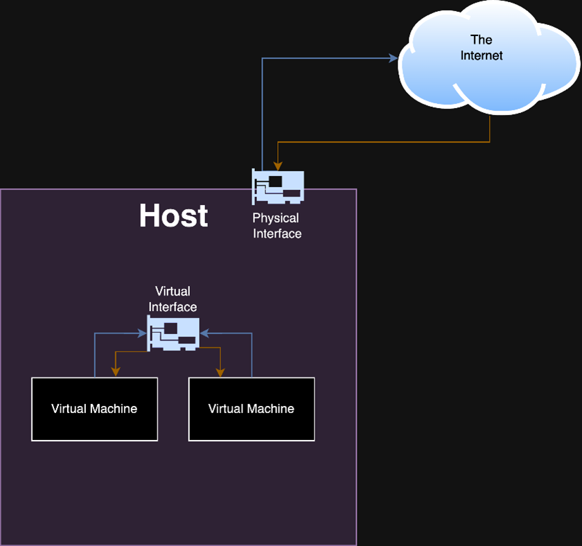
Figure 1: A simplified example of a virtual interface that is not backed by a physical interface. Traffic between virtual machines never leaves the host.
However, there are use cases in which a user might want a virtual interface to be able to send traffic over a physical medium. For those cases, the virtual interface can also be backed by a physical network interface. Behind the scenes, the virtual interface forwards outbound traffic to a physical network interface.
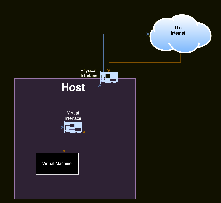
Figure 2: An example of a virtual interface that is backed by a physical interface.
What is a VPN?
A Virtual Private Network (VPN) allows users to create a tunnel for network traffic between their host device and a server on a different network. The resulting virtual network is not confined by geographic location while behaving identically to a physical network.
To achieve this, VPN clients create a virtual network interface and use the underlying file descriptor to encrypt/decrypt traffic at a higher layer before sending it to a physical network interface.
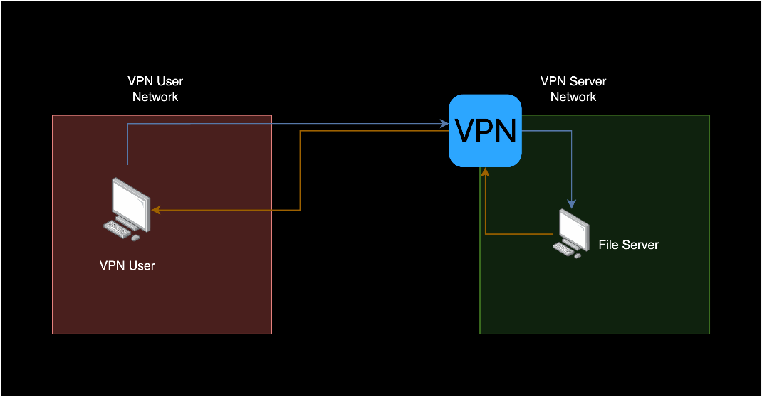
Figure 3: A simplified VPN setup where the VPN user is accessing a resource on a different network.
VPN use is designed to be as simple as possible for a user. Often, they do not need to do much besides log in and click a button to connect to their server.
What a user does:
Select the settings they want on the VPN Client
Click a button to connect
Log in (optional in some cases, depending on the client)
Read the confirmation from the VPN they are connected
Use remote resources from the VPN
Importantly, VPNs actually increase the host’s attack surface because traffic from lower networking layers is send over the Internet. VPNs work by encapsulating lower layers inside of higher layers to create local area networks (LAN) over the Internet. LAN traffic is considered to be more privileged than traffic that is intended to be sent over the Internet. Attackers with LAN access have many more passive and active attack options than an attacker outside of the LAN. By creating a LAN over the Internet, VPNs extend the LAN attack surface to external attackers. Commonly, VPNs mitigate this attack surface by using compensating controls such as packet encryption.
This is an often-misunderstood fact about VPNs. The reason for encryption is not to increase the security of using the physical LAN, but rather to mitigate the added risk that VPNs introduce when they create a virtualized LAN over the Internet. VPNs do not secure you from local network attacks on the physical LAN despite common VPN marketing material and widely given advice.
How do VPNs use virtual network interfaces?
The VPN client process creates an encrypted version of the packet it originally received from the file descriptor associated with its virtual network interface. It places this encrypted payload in the layer for its underlying VPN protocol, then uses that protocol to talk to the VPN server.
| Layer in TCP/IP | Packet 1 (Before encrypted by VPN) | Packet 2 (Encrypted by VPN) |
|---|---|---|
| Data Link Layer | Ethernet: Sender network card: [Physical interface MAC] Dest. network card: [Router interface MAC] |
Ethernet: Source network card: [physical interface MAC] Destination network card: [Router interface MAC] |
| Network Layer | IP: Source IP: 1.234.56.56.78 Destination IP: 2.34.56.78 |
IP: Source IP: 1.234.56.78 Destination IP: 99.87.65.43 |
| Transport Layer | TCP: Sender port: 43555 Destination port: 80 |
UDP: Sender port: 54232 Destination port: 1194 |
| Application Layer | HTTP: GET google.com |
OpenVPN Protocol: Encrypted payload: Ethernet: Sender network card: [virtual interface] Dest. network card: [server’s interface] IP (packet 1) TCP (packet 1) HTTP (packet 1) |
There’s quite a long process for how a VPN sends that packet to the VPN Server. We are including a more exhaustive list of steps in the Appendix for security researchers or developers who might need even more granular details.
A simplified version of that process:
A VPN client establishes a “control channel” connection to a VPN server. If the VPN features a kill switch, then losing connection to this channel will result in a lockdown
The VPN client creates a virtual network interface
The VPN client optionally runs a startup script to configure the host. It may configure routing rules, the DNS server to use, host-based firewall rules, or other settings
A process on the host attempts to send network traffic to a destination (i.e., Internet browsing)
Routing rules select the VPN’s interface to send the traffic through
The VPN client receives and encrypts that traffic
The VPN client sends the encrypted traffic over a physically backed network interface to the VPN server
The VPN server receives and decrypts that traffic from the VPN client
The VPN server forwards that traffic to the destination. If the destination is outbound, the VPN will send your traffic as though it is its own. This behavior is what VPN providers describe as “IP cloaking” or “IP hiding”
The VPN server receives a reply from the destination, encrypts the response, and sends it to the VPN client
The VPN client decrypts the response, and the originating process finally receives the traffic
It can be quite hard to understand fully since there are many steps involved. For that reason, we’ve made our own detailed diagram of a mental model we use for how a VPN client sends and receives information (Figure 4).
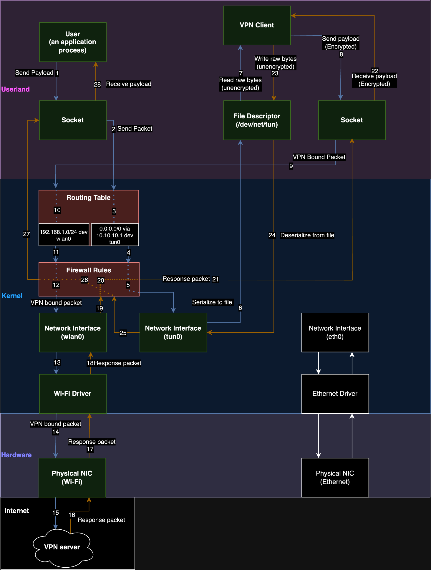
Figure 4: A dataflow diagram of a VPN on a Linux host.
How do routing based VPNs configure a host?
Once a user connects to a VPN server, their VPN client process will configure the host’s settings to route traffic through the tunnel that it established. If all traffic* is routed through the VPN, we refer to it as a “full-tunnel VPN”. If there are user-defined exceptions for traffic, such as local network traffic, we refer to it as a “split-tunnel VPN”. The VPN client can also configure other settings on the host, such as the host’s firewall. Later, we’ll discuss a mitigation we observed using the host-based firewall.
Commonly, these configuration changes are made by “up scripts” and “down scripts” when a connection is established or disconnected. The runtime process for a VPN client may also perform configuration changes, but this varies from vendor to vendor.
*Note: When we say, “all traffic”, we really mean “all traffic except the traffic necessary to keep the VPN in a working state.” For example, VPNs create an exception to their own previously configured routing rules. All traffic sent to the VPN servers IP address must be sent over a hardware backed interface instead of its own tunnel. Otherwise, it would break the hosts connection to the VPN server and the VPN client would be unable to send encrypted packets. In addition, there are other configuration exceptions made for DHCP traffic since the VPN must maintain its hosts IP address lease.
What are routes and routing tables?
Routes are how we describe where to send traffic based on the destination. Routing tables are a collection of routes that are used by the network stack. Consider a network stack to just be all the code on an operating system that deals with sending and receiving data from a network.
A common route is sending all traffic (0.0.0.0/0 in Classless Inter-Domain Routing [CIDR] notation) to your router (192.168.1.1) over the physical network interface (eth0).
An example of that rule in the table would be:
0.0.0.0/0 via 192.168.1.1 dev eth0Another behavior of routing tables is that by default (in most network stacks) the most specific prefix length for the CIDR range has the highest priority. The prefix length for the range 192.168.1.1/32 is 32 and the prefix length for the range 0.0.0.0/0 is 0. The highest numerical value of a prefix length will take priority for routing selection (unless configured otherwise).
For example:
0.0.0.0/0 via 192.168.1.1 dev eth0
10.10.10.1/24 via 192.168.1.1 dev wifi1
10.10.10.2/32 via 192.168.1.2 dev eth0
In this situation, if we sent traffic to 10.10.10.2, the most specific rule is the /32 rule and it would therefore be the rule the network stack uses despite matching the other two rules above it.
Most full-tunnel VPNs use the least specific rule possible to capture all traffic. Note that the following example includes an exception route for the hypothetical VPN server address (12.34.56.78) as well.
0.0.0.0/0 via 10.13.37.1 dev tun0
12.34.56.78/32 via 192.168.1.1 dev eth0
Alternatively, providers may use two /1 rules to gain priority over the default route. It's common in even non-adversarial environments for DHCP to set a default route to the physical gateway.
0.0.0.0/0 via 192.168.1.1 dev eth0
0.0.0.0/1 via 10.13.37.1 dev tun0
128.0.0.0/1 via 10.13.37.1 dev tun0
12.34.56.78/32 via 192.168.1.1 dev eth0
What is DHCP?
DHCP was originally developed as a robust way to dynamically issue IP addresses to devices on a local network as opposed to manually addressing each device. All modern operating systems have their own DHCP client that will automatically request an IP address.
The main concept to understand is that DHCP provides a time-based lease for IP addresses, and it contains many additional features called options that allow you to adjust the configuration of devices remotely and dynamically. Some notable options include setting the default gateway that acts as the primary route to the Internet or DNS (Domain Name System) servers, which resolve domain names like “google.com” to an IP address.
A client who wants an IP address uses a broadcast to send a DHCPDISCOVER packet to the entire local subnet. Other hosts will ignore this, except for the server who will respond with a DHCPOFFER unicasted directly to the client to offer it a time-bound lease.
Alternatively, if a client knows who the DHCP server is, it has the option to unicast the DHCPDISCOVER to a DHCP server instead of broadcasting. Usually, this is used for renewing its lease.
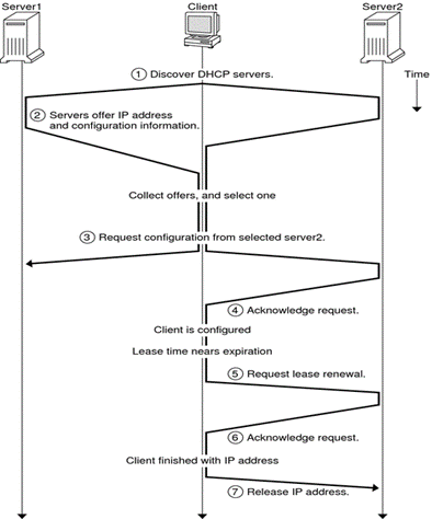
Figure 5: How a DHCP client obtains an IP address and then maintains its lease.
As seen in the above diagram, once a DHCP server makes an offer, the client can choose to accept or decline the offer. For example, if it receives multiple offers, it will choose the best one. The selection most often implemented by DHCP clients is “first come, first serve.” The servers that aren’t selected will be sent a DHCPDECLINE message from the client. Notably, the DHCPOFFER will include the options.
What is DHCP option 121?
In 1997, the DHCP RFC had option 33, which allowed network administrators to specify a static route to install into a client’s routing table. However, this used classful static routes, which fell out of favor over time as public IP space became limited. In 2002, RFC 3442 introduced option 121 classless static routes and obsoleted option 33 (which still should be supported, depending on who you ask). Option 121 also allows administrators to add static routes to a client’s routing table, but with classless ranges instead. There is no limit besides packet size to how many different routes can be installed at once.
An interesting quirk of DHCP option 121 is that the network interface device for the route it installs cannot be specified by the DHCP server. Below you can see a DHCPOFFER packet that was captured in Wireshark. It specifies the CIDR range and the router to use but has no interface device.
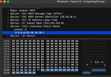
Figure 6: A DHCPOFFER packet that includes an option 121 route. The network interface is not specified by design.
Instead, the DHCP client will implicitly choose the network interface that the client is talking to the DHCP server on when installing its routing rules for this option.
Decloaking Attacks
Requirements for decloaking VPN traffic
The targeted host must accept a DHCP lease from the attacker-controlled server
The targeted host’s DHCP client must implement DHCP option 121
We want to stress that there are ways an attacker who is on the same network as a targeted user might be able to become their DHCP server:
A rogue DHCP server using a DHCP starvation attack against the true DHCP, then responding to new clients. We have achieved this in lab environments and are working on a follow-up blog post.
A rogue DHCP server racing to respond to DHCPDISCOVER broadcasts to abuse DHCP clients’ common behavior where they implement first-offer lease selection.
ARP spoofing to intercept traffic between the true DHCP server and client, then waiting for a client to renew their lease.
Performing the attack
Our technique is to run a DHCP server on the same network as a targeted VPN user and to also set our DHCP configuration to use itself as a gateway. When the traffic hits our gateway, we use traffic forwarding rules on the DHCP server to pass traffic through to a legitimate gateway while we snoop on it.
We use DHCP option 121 to set a route on the VPN user’s routing table. The route we set is arbitrary and we can also set multiple routes if needed. By pushing routes that are more specific than a /0 CIDR range that most VPNs use, we can make routing rules that have a higher priority than the routes for the virtual interface the VPN creates. We can set multiple /1 routes to recreate the 0.0.0.0/0 all traffic rule set by most VPNs.
Pushing a route also means that the network traffic will be sent over the same interface as the DHCP server instead of the virtual network interface. This is intended functionality that isn’t clearly stated in the RFC. Therefore, for the routes we push, it is never encrypted by the VPN’s virtual interface but instead transmitted by the network interface that is talking to the DHCP server. As an attacker, we can select which IP addresses go over the tunnel and which addresses go over the network interface talking to our DHCP server.

Figure 7: A malicious DHCP option 121 route that causes traffic to never be encrypted by the VPN process.
We now have traffic being transmitted outside the VPN’s encrypted tunnel. This technique can also be used against an already established VPN connection once the VPN user’s host needs to renew a lease from our DHCP server. We can artificially create that scenario by setting a short lease time in the DHCP lease, so the user updates their routing table more frequently. In addition, the VPN control channel is still intact because it already uses the physical interface for its communication. In our testing, the VPN always continued to report as connected, and the kill switch was never engaged to drop our VPN connection.
Proof of Concept
Video proof of concept:
Lab Setup Code:
DHCP Server image:
The lab scenarios are built to represent:
An attacker compromises a DHCP server/access point
A rogue administrator owns the infrastructure themselves and maliciously configures it
An attacker sets up an evil twin wireless AP in a physical location such as a coffee shop or corporate office
One we release our tool, ArcaneTrickster, the lab can also be used to mimic an attacker who has an adjacent host on the network na dis otherwise not in a privileged network position
Fixes
Network Namespaces
Using network namespaces on Linux can completely fix this behavior. However, in our experience, it is less commonly implemented.
WireGuard’s documentation shows how it’s possible to use a namespace for all applications with traffic that should be using a VPN before sending it to another namespace that contains a physical interface. However, this appears to be Linux-specific functionality and it’s not clear if there is a solution for Windows, MacOS, or other operating systems with the same amount of robustness.
Mitigations
Firewall Rules
We’ve observed VPN providers denying all inbound and outbound traffic to and from the physical interface via firewall rules. An exception was necessary for the DHCP and VPN server IPs because they are necessary to remain connected to the LAN and VPN server. Deep packet inspection could also allow only the DHCP and VPN protocols instead but would likely incur a performance penalty.
Problems with Firewall Rule Mitigations
Firewall mitigations create a selective denial of service for traffic using the DHCP route and introduce a side-channel. An attacker can use this side-channel to determine the destination of traffic. To determine the traffic’s destination, an attacker could perform traffic analysis on the volume of VPN encrypted traffic a user sends. The attacker would need a baseline volume of traffic where no malicious are installed. Then the attacker would need to modify the lease configuration to install routes that deny traffic and observe the difference in volume.
With enough samples, it would be possible to statistically prove whether the targeted user is sending traffic to a specific destination. For the average internet user, most internet traffic is already secured by TLS. Therefore, traffic intercepted by TunnelVision will mostly be unreadable except for the destination and protocols. This means that this side-channel has nearly the same impact and should be considered insufficient.
The side-channel is flexible in use:
The traffic can be checked against a predefined list.
The traffic can be selectively denied as a censorship mechanism.
The attacker can use IP space denial with binary search to determine all current connections in logarithmic time.
Ignore Option 121
Another possible mitigation is ignoring option 121 while the VPN is on. We noted that because Android does not implement support for DHCP option 121, it was uniquely unaffected. The downside is that option 121 exists for a reason, and ignoring these routes can break network connectivity (something that is frequently brought up as a reason to implement it on Android). If this mitigation is implemented, it must be mandatory because attackers could simply deny network access until the VPN or user re-enables option 121.
Use a Hot Spot or VM
Hot spots are temporary Wi-Fi networks controlled by a cellular device. They create a password-locked LAN with automatic network address translation. Because this network is completely controlled by the cellular device and requires a password, an attacker should not have local network access. A virtual machine would also work similarly as long as the VM’s network adapter is not in bridged mode.
Do not use untrusted networks if you need absolute confidentiality of your traffic
Industry Impact
Is TunnelVision a vulnerability?
This is debatable. We’re calling it a technique because TunnelVision doesn’t rely on violating any security properties of the underlying technologies. From our perspective, TunnelVision is how DHCP, routing tables, and VPNs are intended to work.
However, it contradicts VPN providers’ assurances that are commonly referenced in marketing materials; in our opinion, TunnelVision becomes a vulnerability when a VPN provider makes assurances that their product secures a customer from an attacker on an untrusted network. There’s a big difference between protecting your data in transit and protecting against all LAN attacks. VPNs were not designed to mitigate LAN attacks on the physical network and to promise otherwise is dangerous.
In our technique, we have not broken the VPN’s cryptographically secured protocol, and the VPN is still fully functional. An attacker is instead forcing a target user to not use their VPN tunnel. Regardless of whether we classify this as a technique, VPN users are affected when they rely on assurances that a VPN can secure them from attackers on their local network.
Affected Operating Systems
In our testing, we observed that any operating system that implements a DHCP client according to its RFC specification and has support for DHCP option 121 routes is affected. This includes Windows, Linux, iOS, and MacOS. Notably, it does not affect Android as they do not have support for DHCP option 121.
Affected VPN Providers and VPN Protocols
We found that VPNs that solely rely on routing rules to secure the host’s traffic are vulnerable. Those who are hosting their own VPN servers (e.g., system administrators) and are not hardening their VPN client configurations will likely be vulnerable as well. We have observed a mitigation from some VPN providers that drops traffic to non-VPN interfaces via firewall rules. It’s possible there are other methods that we did not encounter during testing to mitigate or fix this.
As previously mentioned, we observed the same behavior on each operating system we tested, save one. Furthermore, the strength of the encryption algorithm a VPN uses makes no difference. TunnelVision’s effect is independent of the underlying VPN protocol (e.g., WireGuard, OpenVPN, or IPsec) because it reconfigures the operating system network stack the VPN relies on.
Conclusion
Call to Action
We have a limitation as a research team of two– there are simply too many VPNs on the market to test each one individually. The first approach we took was to notify companies via bug bounties or security disclosure email, but that quickly became unscalable. We’ve also engaged the EFF and CISA to help disclose as broadly as possible prior to publicly releasing this research. We thank them tremendously for their help. Our hope is that by publishing our work, we can reach more affected parties, especially because we believe the technique has been feasible since as early as 2002.
Although the public disclosure of this technique affects each party differently, ultimately there is a shared responsibility.
Users should be made aware of this technique and for sensitive traffic they should be warned against using untrusted networks. If they must use an untrusted network, they should use a VPN provider that has an effective mitigation against this technique. To determine if a provider has an effective mitigation or fix, our lab setup is available for testing and VPN providers themselves will be able to speak to the specifics of their existing mitigations in their documentation. If a VPN decloak does occur, most user data will not be visible to local network attackers assuming they are accessing websites with HTTPS, which has become increasingly common.
It is common for corporate VPNs to be used in areas such as coffee shops, hotels, or airports. Network administrators should inform employees that working from such places carries risks and should be avoided when possible. If such a policy is not practical, then administrators should advise using VPNs that enable the previously mentioned mitigations or fixes. Some alternatives would be to use a trusted hot spot and then connect to the VPN. Lastly, running the VPN inside of a VM that obtains a lease from a virtualized DHCP server would prevent the local networks DHCP server from installing routes altogether.
Companies that control their own networks or have site-to-site VPNs should review the switches they use and enable features such as DHCP snooping and ARP protections. These layer 2 protections help prevent rogue DHCP servers but do not eliminate a rogue administrator scenario. In addition, implementing HTTPS or other protocols with encryption for internal resources will prevent data leakage from VPN users connecting from untrusted networks.
VPN providers can add features to clients to configure firewall rules that drop outbound packets to network interfaces. However, such a setting will mean that a VPN user will be isolated from interacting with local network resources. If the VPN client is for Linux and is intended to be a full tunnel, using network namespaces for isolation. As such, VPN providers should publicly provide documentation about any mitigations or fixes they have for TunnelVision and warn their end users about TunnelVision’s existence. We also recommend reviewing their marketing material and cease marketing claims that VPNs protect customers on untrusted networks until it can be proven.
Operating system maintainers (outside of Linux) should determine whether adding or enhancing features related to network namespaces is feasible.
Upcoming Research
During the disclosure process, we encountered multiple cases in which the entities we disclosed to did not see this as a serious problem. They assumed that the prerequisite conditions included privileged positions or accounts, despite the only prerequisite being local network access. This assumption was partially fueled by our intentionally simplistic lab setup where we were the only DHCP server, and what we perceive as the entity’s lack of familiarity with low-level networking.
With this feedback, we decided to develop a robust adversarial infrastructure library to enable further LAN security research and demonstrate practical attacks. For example, we can demonstrate that it’s possible to consistently perform TunnelVision while simply being adjacent to the target host on the same LAN. We’re calling it “ArcaneTrickster” and plan on releasing it at a later date. However, we feature a demo in our videos, which are available in the proof of concept section.

Let Us Know
If you have questions or are interested in learning about how Leviathan Security Group can help you achieve your security goals, head over to our contact page and submit our short form.
Our team will reach out to you to schedule a time to learn more about your initiatives and priorities.
Credits
Authors:
Lizzie Moratti
Dani Cronce
Acknowledgements:
Sofia Aberegg
TC Johnson
Brian Campbell
Martin Bogomolni
Brad “Renderman” Haines
Frank Heidt
Special Thanks to:
Electronic Frontier Foundation (EFF)
United States Cybersecurity Infrastructure and Security Agency (CISA)
Appendix
Prior research related to TunnelVision
We found research related to DHCP leaking default routes over an incorrect interface as far back as 2015. However, it was implied that DHCP only pushed default routes and did not account for DHCP option 121.
In August 2023, a paper was published demonstrating that routing rules can be attacked in different ways to leak VPN traffic. The paper details two methods of leaking VPN traffic:
Abusing non-RFC1918 IP ranges to leak traffic.
DNS spoofing the VPN server’s domain name to trick the VPN client into adding a routing rule exception for an IP address.
However, neither technique described in the August 2023 paper leveraged DHCP option 121 to push routes. Pushing routes through DHCP has a significantly higher impact from the same attacker vantage point (the ability to hand out IP leases for a non-RFC1918 range or spoofing DNS replies).
In-Depth Diagram Explanation
For posterity and because we haven’t encountered another diagram like ours (Figure 4), below are the steps from the diagram in as much detail as we could reasonably provide. We feel it could be useful to a future security researcher or a developer trying to understand the technology, so we are including it for their benefit.
An application process sends a payload to a socket it creates.
The socket formats the payload into a packet and sends it to the routing table to determine which interface it should be sent through.
The routing table determines that the packet should be sent through tun0.
The routing table sends the packet to the firewall.
The firewall rules allow the packet to continue to tun0.
The network interface serializes the packet and writes it into a file descriptor at /dev/net/tun in userland.
The VPN client process reads the unencrypted raw bytes of the packet in the file descriptor.
The VPN process creates an encrypted payload and sends it to a socket the VPN made.
The socket formats the payload into a packet that is bound for the VPN’s server and sends it to the routing table to determine which interface it should be sent through.
The routing table determines that the packet must be sent over the wlan0 interface.
The routing table sends the packet to the firewall.
The firewall rules determine that the outbound packet may continue using wlan0.
The network interface transfers the packet to its Wi-Fi driver.
The Wi-Fi driver sends the VPN-bound packet to the physical network interface card (NIC).
The packet is sent across the internet to the VPN server.
The VPN server sends a packet in response back to the physical NIC.
The NIC sends the response packet to the Wi-Fi driver.
The Wi-Fi driver delivers the response packet to wlan0.
The response packet is sent to the firewall.
The firewall rules allow the packet to continue.
The packet is returned to the VPN socket.
The socket receives the packet and sends the packet’s encrypted payload to the VPN client process.
The VPN client process decrypts the payload and writes the unencrypted raw bytes of the response packet to the file descriptor.
The tun0 interface deserializes the bytes from the file descriptor and formats it into a packet.
The tun0 interface sends the packet to the firewall.
The firewall rules allow the packet to continue.
The packet is returned to the socket opened by the user’s application process.
The payload from the packet is returned to the application process.